|
|
|
|
|
| |
Mech-Controller ... |
| |
|
| |
|
|
|
|
|

Manual
/
Wiring
Diagram
|
|
|
Hand
Shut
Off
Valves |
| |
|
|
| Application |
► |
These diaphragm type hand shut off valves are designed for installations in liquid, suction and hotgas lines of commercial refrigerating systems and on civil and industrial
air-conditioning systems. |
| |
| Construction |
► |
Diaphragm valves don’t have gland seals. The external sealing is assured by thin metal discs (diaphragms), which hermetically divide the spindle chamber from the fluid flow area. |
| |
|
The main parts of the valves are made with the following materials |
|
► |
Hot forged brass body as per BS-218 |
|
► |
Extruded brass for the spindle |
|
► |
Special spring steel for the spring |
|
► |
Engineering Plastics for seat sealing gaskets |
|
| |
|
|
| Features |
► |
Can be used on all CFC’s and HCFC’s |
| |
► |
Seat of Engineering Plastics to give complete shut off with minimum torque |
| |
► |
Fitted with stainless steel diaphragms that prevent leakage |
| |
► |
Throughout the operating life of the valve |
|
|
|
| |
| |
|
Model |
Size
Flare |
Size OD |
Operating
Temp |
Operating
Pressure |
| 0C Min |
0C Max |
PSI
(Max) |
|
CSV
- 6 |
1/4" |
|
-35 |
90 |
400 |
|
CSV
- 6
S |
|
1/4" |
|
CSV
- 10 |
3/8" |
|
|
CSV
- 10
S |
|
3/8" |
|
CSV - 12 |
1/2" |
|
|
CSV
- 12
S |
|
1/2" |
|
CSV
- 15 |
5/8" |
|
|
CSV
- 15
S |
|
5/8" |
|
| |
| |
|
| |
| |
Angle Valve
(Receiver Valve) |
|
|
|
|

Manual
/ Wiring Diagram
|
|
Application |
► |
These
receiver
valves
are
designed
for
installation
on
commercial
refrigerating
systems
and
on
civil
and
industrial
air-conditioning
systems.
They
are
suitable
for
all
refrigerant
fluids
except
Ammonia. |
|
|
|
Construction |
|
The
main
parts
of
these
valves
are
made
with
the
following
materials
: |
| |
► |
Hot
forged
brass
as
per
BS-218 |
| |
► |
Steel
with
proper
surface
protection,
for
the
spindle |
| |
► |
Neoprene
rubber
for
the
gland |
| |
► |
Engineering
Plastics
for
the
cap
that
covers
the
spindle |
| |
|
|
|
| Operating Temp |
Operating Pressure |
| 0C Min |
0C Max |
PSI (Max) |
| -35 |
90 |
400 |
|
| |
| Model |
Connection |
| CAV- 76 |
1/4" Flare |
1/4" NPT |
| CAV- 66 |
1/4" Flare |
1/4" Flare |
| CAV- 98 |
3/8" Flare |
3/8" Flare |
| CAV- 99 |
3/8" Flare |
3/8" NPT |
|
| Model |
DIMENSIONS(MM) |
Weight |
| H 1 |
H 2 |
L 1 |
gm |
| CAV- 76 |
67 |
44.5 |
26 |
80 |
| CAV- 66 |
67 |
44.5 |
26 |
80 |
| CAV- 98 |
75 |
48 |
31 |
120 |
| CAV- 99 |
75 |
48 |
31 |
120 |
|
|
|
| |
|
| |
|
| |
Angle Shut Off
Valves (ODS) |
|
|
|

Manual
/ Wiring Diagram
|
|
Application |
► |
These
angle
shut
off
valves
are
designed
for
installation
on
commercial
refrigerating
systems
and
on
civil
and
industrial
air-conditioning
systems.
They
are
amongst
many
applications,
used
to
isolate
various
devices
like
driers,
receivers
etc.
They
have
large
orifices
to
keep
pressure
drops
to a
minimum.
These
valves
are
suitable
for
all
CFC’s
and
HCFC’s
except
Ammonia. |
|
|
|
Installation |
► |
The
brazing
of
these
valves
with
solder
connections
should
be
carried
with
care
using
a
low
melting
point
filler
material.
|
|
|
|
Construction |
► |
Investment
Cast
Body
-
CF.8
/S.S.304 |
| |
► |
Spindle
-
Steel |
| |
► |
Seat
-
Steel |
| |
► |
Gland
packing
-
99%
Graphite |
| |
► |
Springl
-
S.S. |
|
| |
|
| Model |
Size ODS |
Operating Temp |
Operating Pressure |
| 0C Min |
0C Max |
PSI(Max) |
| CAV - 32 |
1.3/8" |
-35 |
90 |
400 |
| CAV - 32 |
1.5/8" |
| CAV - 50 |
2.1/8" |
|
|
| |
|
| |
|
| |
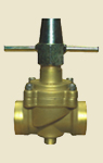
Globe Valves |
|
|
|
Manual
/ Wiring Diagram
|
|
Application |
► |
These
globe
valves
are
designed
for
installation
on
commercial
refrigerating
systems
on
civil
and
industrial
air-
conditioning
systems.
They
are
amongst
many
applications,
used
to
isolate
various
devices
like
driers,
receivers
etc.
They
have
large
orifices
to
keep
pressure
drops
to a
minimum.
These
valves
are
suitable
for
all
CFC’s
and
HCFC’s
except
Ammonia.
They
can
be
used
to
Isolate
a
drier
or
similar
device. |
|
|
|
Installation |
► |
The
brazing
of
these
valves
with
solder
connections
should
be
carried
with
care
using
a
low
melting
point
filler
material.
It
is
necessary
to
remove
the
bonnett
assembly
with
spindle
and
cap
prior
to
brazing
the
valve.
Re-assemble
the
valve
only
once
the
valve
has
cooled
completely
and
reached
room
temperature. |
| |
|
|
|
|
| |
|
Model |
DIMENSIONS
(MM) |
|
H |
H1 |
L |
Q |
A |
M |
|
CGV-15 |
135 |
27 |
81 |
55 |
97 |
5/16"BSW |
|
CGV-22 |
135 |
27 |
81 |
55 |
97 |
5/16"BSW |
|
CGV-28 |
145 |
32 |
82 |
60.5 |
100 |
3/8"BSW |
|
CGV-32 |
160 |
35.5 |
96 |
70 |
100 |
3/8"BSW |
|
CGV-40 |
179 |
38 |
101 |
74 |
130 |
3/8"BSW |
|
CGV-40 |
240 |
40 |
132 |
87 |
146 |
5/16"BSW |
|
| |
|
Model |
Size
ODS |
Operating
Temp |
Operating
Pressure |
| |
|
0C
Min |
0C
Max |
PSI(Max) |
|
CGV
- 15 |
5/8" |
-35 |
90 |
400 |
|
CGV
- 20 |
7/8" |
|
CGV
- 28 |
1.1/8" |
|
CGV
- 32 |
1.3/8" |
|
CGV
- 40 |
1.5/8" |
|
CGV
- 50 |
2.1/8" |
|
CGV
- 80 |
3.1/8" |
|
CGV
- 90 |
3.5/8" |
|
CGV
-
100 |
4.1/8" |
|
| |
|
| |
|
| |
| |
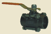
Ball Valves |
|
|
|
Manual
/ Wiring Diagram
|
|
Application |
►
|
Petroleum,
Petrochemical,
Chemical,
Refrigeration,
Air-conditioning
and
engineering
industries.
Valves
are
compatible
with
Ammonia,
CFC,
HCFC,
Oil,
Air,
Chemicals,
Gas,
Acids,
Alkalies
etc.
amongst
many
other
media. |
|
|
|
Installation |
► |
The
three
piece
design
makes
the
Series
C-44
valve
the
most
easily
maintainable
valve
in
its
type.
By
removing
three
body
connector
bolts
and
loosening
the
fourth,
the
body
can
be
swung
away
using
the
fourth
bolt
as a
fulcrum,
to
carry,
out
any
maintenance
on
the
valve.
This
feature
allows
the
valve
to
be
online
and
considerably
reduces
down
time. |
| |
|
|
|
| |
|
|
MATERIAL SPECIFICATIONS |
Name Of
Part |
Carbon Steel
Valve |
Stainless Steel
Valve |
| Body |
ASTM-A352
L.C.B |
ASTM A351
Gr.CF 8 |
| Body Connector |
| Ball |
AISI 304 Gr.CF 8 |
| Seat |
Virgin PTFE |
| Stem |
Stainless Steel AISI 304
Virgin PTFE |
| Body Seal |
| Gland Pancking |
35% Carbon Filled PTFE |
| Stem Seal |
|
| |
|
Model |
SCREWED/ SOCKET-WELD END (IN MM, UNLESS SPECIFIED |
|
Weight |
| DN |
INCH |
A |
B |
C |
D+0.25 |
E |
H |
Kg |
| DN15(1/2") |
1/2" - 5/8" |
64 |
45 |
122 |
21.8 |
9.7 |
11.2 |
0.6 |
| DN20(3/4") |
7/8" |
75 |
54 |
122 |
27.4 |
12.7 |
14.2 |
1 |
| DN25(1") |
1.1/8" |
94 |
75 |
148 |
34.1 |
12.7 |
22 |
1.7 |
| DN32(1.1/4") |
1.3/8" |
109 |
73 |
182 |
42.7 |
12.7 |
25 |
2.5 |
| DN40(1.5") |
1.5/8" |
118 |
73 |
182 |
49 |
12.7 |
32. |
3.7 |
| DN50(2") |
2.1/8" |
127 |
83 |
182 |
61 |
12.7 |
38 |
5 |
| DN65(2.5") |
2.5/8" |
145 |
260 |
230 |
77.5 |
15.9 |
50 |
8.5 |
| DN80(3") |
3.1/8" |
172 |
280 |
230 |
91 |
20 |
63 |
11.5 |
| DN100(4") |
4.1.8" |
185 |
295 |
230 |
117.5 |
25 |
72 |
18 |
| DN125(5") |
5.1/8" |
230 |
295 |
230 |
142 |
25 |
96 |
25 |
|
|
| |
|
| |
|
| |
Non Return Valve
(Check Valve) |
|
|
|

Manual
/ Wiring Diagram
|
|
Application |
► |
These
check
valves
are
designed
for
installation
in
liquid,
suction
and
hotgas
lines
on
commercial
refrigerating
systems
and
on
civil
and
industrial
air-conditioning
systems. |
|
|
|
Construction |
|
The
main
parts
of
the
valves
are
made
with
the
following
materials
: |
|
|
► |
extruded
brass
as
per
BS-218 |
|
|
► |
stainless
steel
for
the
spring |
|
|
► |
neoprene
rubber
for
outer
seal |
|
|
► |
PTFE
for
seat
|
|
|
|
Installation |
► |
The
valves
can
be
installed
in
any
section
of a
refrigerating
system,
where
it
is
necessary
to
avoid
an
inversion
of
the
refrigerating
flow.
Before
connecting
the
valve
to
the
pipe
it
is
to
make
sure
that
the
refrigerating
system
is
clean.
Infact
the
valves
with
PTFE
seats
are
particularly
sensitive
to
dirt
and
debris.
Furthermore
check
that
the
flow
direction
in
the
pipe
corresponds
to
the
arrow
stamped
on
the
body
of
the
valve. |
|
| |
|
| Model |
DIMENSIONS |
Weight |
| |
H |
D |
gm |
| NRV- 6 |
58.5 |
25.4 |
90 |
| NRV- 10 |
61 |
25.4 |
100 |
| NRV- 12 |
72 |
29 |
150 |
| NRV- 15 |
83 |
36.5 |
230 |
|
| |
| |
|
Operating Temp |
Operating Pressure |
| Model |
Size Flare |
0C Min |
0C Max |
PSI (Max) |
| NRV - 6 |
1/4" |
-35 |
90 |
400 |
| NRV - 10 |
3/8" |
| NRV - 12 |
1/2" |
| NRV - 15 |
5/8" |
|
|
| |
| |
| |
Pilot Operated
solenoid Valve |
|
|
|

Manual
/ Wiring Diagram
|
|
Principles
of
operation |
► |
The
principle
upon
which
the
180
Solenoid
Pilot
Control
influences
the
expansion
valve
action
is
by
the
creation
of a
pressure
under
the
valve
diaphragm
which
is
higher
than
the
bulb
pressure.
This
is
how
it
is
accomplished.
The
type
180
has
two
parts,
both
in
the
the
valve
body-one
high
pressure
and
one
low
pressure.
When
the
solenoid
coil
is
energized,
the
plunger
moves
upward
sealing
off
the
high
pressure
port.
With
the
high
pressure
excluded
from
the
pilot
control,
true
suction
pressure
acts
on
the
underside
of
the
expansion
valve
diaphragm
through
the
equalizer
line
and
the
low
pressure
port.
When
the
solenoid
coil
is
de-energized,
the
low
pressure
port
is
closed,
thereby
closing
the
equalizer
line
from
the
valve
to
the
suction
line.
The
high
pressure
port
is
open
and
liquid
line
pressure
is
applied
to
the
underside
of
the
thermostatic
expansion
valve
diaphragm.
This
high
side
pressure
instantly
overcomes
the
bulb
pressure
and
supplements
the
valve
spring,
immediately
closing
the
port
of
the
expansion
valve. |
|
|
|
Application |
► |
The
type
180
Solenoid
Pilot
Control
suitable
for
all
refrigerants
except
Ammonia
The
180
Solenoid
Pilot
Control
is
applicable
for
Refrigerants
12,22,500
and
502,
as a
supplementary
device
to
Thermostatic
Expansion
Valves.
It
is
used
in
place
of
capacity
solenoid
valves
for
positive
shut-off
of
liquid
lines.
The
Solenoid
Pilot
Control
does
not
directly
close
the
liquid
line,
but
acts
on
the
thermostatic
expansion
valve
causing
the
expansion
valve
to
close.
The
180
is
installed
in
the
external
equalizer
line
of
the
thermostatic
expansion
valve,
and
has
a
third
1/4
"connection
from
the
liquid
line. |
|
| |
|
| |
|
| |
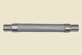
Vibration
Absorber |
|
|
|
Manual
/ Wiring Diagram
|
|
Application |
►
|
Both
the
suction
and
discharge
lines
transmit
vibration
from
the
compressor
to
the
other
cooling
system
components
and
the
building.
This
vibration
can
cause
unwanted
noise
and
deterioration
of
tubing,
leading
to
leaks
of
refrigerant
and
capillary
tube
control
fluids.
The
vibration
absorber
consists
of a
special
flexible
metallic
hose
with
an
overbraid.
The
end
connections
may
be
of
solder
connections,
flanges
or
threaded
male
ends.
Refrigerant
travelling
too
quickly
along
with
convolouted
inner
diameter
of
the
absorber
may
cause
whistling.
Vibration
absorbers
eliminate
the
need
of
looping
copper
tubing
to
avoid
vibration.
Vibration
absorbers
are
not
designed
for
compression
or
extention,
so
they
must
be
oriented
parallel
to
the
crankshaft,
not
at
right
angles
to
it.
If
the
absorber
is
mounted
improperly,
it
will
resist
the
rocking
of
the
compressor
instead
of
flexing
along
with
it.
For
maximum
control
of
vibration,
two
absorbers
should
be
placed
in
each
line,
one
for
horizontal
movement
and
the
other
for
vertical
movement.
Do
not
stress,
compress
or
twist
the
absorbers
during
installation.
Install
the
unit
as
close
to
the
compressor
as
possible,
and
at
right
angle
to
motion.
Anchor
the
refrigerant
piping,
as
shown
above,
at
the
end
of
the
unit
furthest
from
the
vibration
source.
Also,
install
the
unit
horizontally,
wherever
possible.
Allow
sufficient
space
for
the
unit
so
that
it
will
not
be
subject
to
static
compression
or
tension
after
brazing
it
into
place.
Units
should
be
installed
in a
straight
line;
they
are
not
intended
to
compensate
for
offset
piping.
If
the
unit
is
installed
in
an
area
where
condensate
can
accumulate
on
it,
cover
the
unit
with
a
waterproof
barrier
(such
as
heat
shrinkable
PVC
tubing
or
rubber
tape)
to
prevent
moisture
from
freezing
under
the
braid
and
ferrules,
causing
the
unit
to
rupture. |
|
|
|
Construction |
► |
Hose
:
Stainless
Steel
304 |
| |
► |
Braid
:
Stainless
Steel
321
|
| |
► |
End
connection
:
Copper |
|
|
|
Installation |
►
|
Castle
vibration
absorbers
function
best
when
installed
as
close
to
the
compressor
as
possible
and
perpendicular
to
the
major
vibration
direction
as
possible.
Although
the
copper
tube
ends
of
the
unit
are
attached
by
high
temperature
brazing
alloys
having
a
high
melting
point,
care
should
nevertheless
be
exercised
when
making
the
sweat
connections.
Direct
the
torch
flame
away
from
the
braid.
Clean
excess
flux
from
the
unit
to
prevent
possible
corrosion
and
premature
failure.
For
situations
of
severe
vibration,
install
two
units
in
series
at
right
angles
to
one
another
as
shown
in |
|
| |
|
| |
|
| |
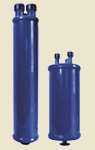
OS Series Oil
Separator |
|
|
|
Manual
/ Wiring Diagram
|
|
Features |
► |
Hermetic
welded
construction
with
steel
oil
return
relief
(1/4”
or
3/8”
SAE
connectors) |
| |
► |
Maximum
working
pressure:
450
PSI |
|
|
|
Part-
|
► |
ODF |
|
description |
► |
Mesh |
| |
► |
Resister |
| |
► |
Oil
concentrator |
| |
► |
Floating
Ball
|
| |
► |
Needle
valves |
|
| |
|
|
Specifications |
|
|
|
| Model |
ODF
(IN) |
Dimensions |
Refrigeration Capacity (KW) under the appointed temperature |
| R22/R407C |
R502 |
R134a |
R404A/R507 |
| L(in) |
A(in) |
-400c |
+50C |
-400c |
+50C |
-400c |
+50C |
-400c |
+50C |
| OS-55824 |
1/2 |
9.44 |
4.00 |
5.31 |
7.08 |
5.31 |
7.08 |
3.54 |
6.2 |
5.31 |
7.0 |
| OS-55833 |
3/8 |
9.44 |
4.00 |
5.31 |
7.08 |
5.31 |
7.08 |
3.54 |
6.2 |
5.31 |
7.0 |
| OS-55855 |
5/8 |
12.79 |
4.00 |
15.9 |
19.5 |
16.8 |
20.36 |
11.5 |
15.9 |
14.16 |
19.0 |
| OS-55877 |
7/8 |
15.74 |
4.00 |
24.8 |
28.3 |
26.6 |
30.09 |
16.8 |
23.0 |
23.01 |
30.0 |
| OS-55889 |
1-1/8 |
16.92 |
4.00 |
31.9 |
37.2 |
33.6 |
40.71 |
23.0 |
30.1 |
30.09 |
38.0 |
| OS-559011 |
1-3/8 |
15.16 |
6.00 |
40.7 |
47.8 |
42.5 |
51.33 |
28.3 |
40.7 |
37.17 |
49.0 |
| OS-559011 |
1-3/8 |
16.93 |
6.00 |
49.6 |
62.0 |
56.6 |
61.95 |
33.6 |
46.9 |
49.56 |
60.0 |
| OS-559213 |
1-5/8 |
16.93 |
6.00 |
56.6 |
63.7 |
70.8 |
84.96 |
41.6 |
56.6 |
61.95 |
81.0 |
| OS-559417 |
2-1/8 |
19.30 |
6.00 |
88.5 |
106.0 |
106.0 |
123.90 |
63.7 |
89.4 |
92.04 |
121.0 |
|
|
| |
|
| |
|
| |
Next... |
|
|
|