|
|
|
|
|
| |
Ammonia Valves controls ... |
| |
|
| |
Ammonia - the refrigerant of
choice
|
| |
The use of ammonia for
cooling applications dates
back to the mid 1800's. By
the early 1900's the use of
ammonia as a refrigerant was
largely perfected in a
closed cycle of evaporation,
compression and
condensation. Since then,
the entire food distribution
chain has come to depend on
the thermodynamic properties
of this crucial refrigerant.
Today, ammonia remains the
refrigerant of choice for
industrial cooling
applications. The preeminent
authority on industrial
refrigeration, the
advantages of ammonia over
various types of freon are
numerous.
|
| |
|
► |
Ammonia costs
less. Not only
is ammonia
significantly
cheaper than the
least expensive
halocarbons, but
because the
density of
ammonia is half
that of
halocarbons,
only half as
much material
needs to be
purchased to
charge a system.
|
|
|
|
► |
Ammonia is more
efficient. Its
mass flow rate
for a given
refrigerating
capacity is 1/7
that of HCFC-22,
meaning only one
1/7 the liquid
needs to be
pumped for a
given
refrigerating
capacity.
Consequently,
the mechanical
pump and pumping
power will be
less in an
ammonia system.
|
|
|
|
► |
Ammonia requires
smaller vapor
line pipe sizes
for large
systems spread
over a large
area due to less
drop in
saturation
temperature
compared to
halocarbons.
|
|
|
|
► |
Ammonia systems
are more
tolerant of
water
contamination
than freon
systems.
However, this is
only a relative
advantage for
small amounts of
water
contamination,
as
concentrations
greater than 100
ppm create
problems in
ammonia systems.
|
|
|
|
► |
Ammonia has more
favorable
heat-transfer
coefficients
than
halocarbons.
Compared to
HCFC-22, ammonia
has the
following
advantages:
a. specific heat
of liquid to
vapor = 4:1
b.latent heat of
vaporization =
6:1 c.liquid
thermal
conductivity =
5.5:1
d.viscosities =
.8:1 e.liquid
density = .5:1
|
|
| |
|
| |
|
| |
| |
Solenoid Valves
for Ammonia |
|
|
|
|

Manual
/ Wiring Diagram
|
|
Application |
► |
These
valves
are
for
Ammonia
duty.
The
MSVA
are
pilot
operated
valves
whilst
the
MDSVA
are
direct
operated
solenoid
valves.
They
are
used
in
many
applications
such
as
cold
stores,
freezers,
chilling
applications
etc. |
|
|
|
Installation |
► |
These
valves
must
be
installed
in
horizontal
positions
with
the
coil
housing
no
more
than
45
degrees
from
the
vertical
position. |
| |
|
|
|
Construction |
► |
The
valve
is
made
up
from
various
metals.
Whilst
stainless
steel
is
used
for
components
like
stems,
plungers,
the
main
body
is
made
from
CI/WCB. |
| |
|
|
|
|
|
| |
| Type |
Flanged
Connection |
Port Size
inches |
MOPD
PSI |
Nominal Liquid Capacity T.R.-
Ammonia Pressure Drop P.S.I. |
Coil Rating |
| AC |
1 |
2 |
3 |
4 |
5 |
Type |
Volt-Hz |
Watts |
| MDSVA 12 |
1/2" |
0.140 |
250 |
8.0 |
11.2 |
13.5 |
16 |
17.5 |
SVC-1 |
230 AC
50/60 |
18 |
| MSVA 12 |
1/2" |
0.450 |
275 |
68 |
91 |
110 |
131 |
143 |
| MSVA 12 |
3/4" |
0.600 |
275 |
75 |
97 |
122 |
145 |
167 |
| MSVA 25 |
1" |
0.950 |
300 |
119 |
169 |
221 |
241 |
266 |
SVC-2 |
| MSVA 25 |
1.1/4" |
1.075 |
300 |
125 |
174 |
225 |
249 |
277 |
| MSVA 40 |
1.1/2" |
1.260 |
300 |
275 |
390 |
500 |
500 |
625 |
|
|
| |
|
| |
|
| |
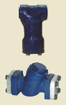
STRAINERS |
|
|
|
Manual
/ Wiring Diagram
|
|
Application |
► |
These
strainers
are
specially
designed
to
be
installed
in
conjunction
with
solenoid
valves.
Their
mesh
is
selected
so
that
no
particles
enter
and
disrupt
the
operation
of
the
solenoid
valve.
For
smooth
operation
of
solenoid
valves
these
strainers
are
mandatory. |
|
|
|
Installation |
► |
For
best
results,
the
strainer
is
installed
right
at
the
inlet
of
the
solenoid
valve
or
as
close
to
it
as
possible
for
larger
sizes. |
|
|
|
Features |
► |
retains
contaminants
e.g.
Slag,
weld
beads,
pipe
fittings.
pressure
drop
insignificant |
|
|
|
Construction |
► |
The
material
of
construction
for
the
body
is
CI
whist
for
the
mesh
it
is
stainless
steel. |
| |
|
|
|
| |
|
| Model |
DIMENSIONS (MM) |
Weight |
| A |
B |
Kg |
| CAS12 |
68 |
122 |
1.3 |
| CAS20 |
85 |
140 |
2.3 |
|
|
|
| Model |
DIMENSIONS (MM) |
Weight |
| A |
B |
C |
D |
E |
F |
G |
H |
PCD |
BOLT SIZE |
Kg |
| CAS25 |
190 |
136 |
42 |
150 |
- |
47 |
58.8 |
4 |
80 |
M12x40 |
7 |
| CAS32 |
190 |
154 |
42 |
150 |
- |
47 |
58.8 |
4 |
80 |
M12x40 |
7 |
|
|
|
|
| |
|
| |
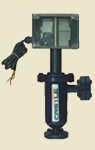
Liquid Level
Controller |
|
|
|

Manual
/ Wiring Diagram
|
|
Application |
► |
While
primarily
designed
for
Ammonia,
this
control
is
also
suitable
for
R-22
and
other
non-corrosive
liquids
that
have
a
specific
gravity
of
0.5
or
more.
The
controller
is
ideal
for
the
control
of
the
operating
level
of
liquid
in
liquid
refrigerant
accumulators
and
separators.
Although
this
is
normally
done
with
a
solenoid
valve,
the
controller
can
activate
an
alarm
or a
pump
or
similar
device. |
|
|
|
Construction |
► |
Mechanical
Float:
Light
deep
drawn
body,
drawn
in
one
piece.
Ball
&
Stem
are
made
from
SS.
Electronic
control
box
made
from
ABS
in
an
international
size
96X96
housing.
This
device
consists
of
two
separate
units,
the
float
chamber
and
the
electronic
controller.
The
float
chamber
consists
of a
housing,
float
ball,
float
coil
and
coil
enclosure.
The
float
ball
is
located
inside
the
housing
and
moves
an
attached
magnetic
stem
up
or
down
in
an
enclosing
tube
from
the
top
and
is
protected
by
the
coil
enclosure.
The
construction
permits
all
high
voltage
connections
and
wiring
to
be
made
at a
remote
or
non-hazardous
location.
Gravity
equalisation
of
the
liquid
level
lin
the
float
chamber
is a
function
of
the
liquid.
For
fluids
having
a
high
viscosity
the
response
time
will
be
slower.
The
level
controller
should
not
be
used
on
water
applications. |
| |
|
|
|
|
| |
|
| |
| |
Liquid Level
Switch |
|
|
|
Manual
/ Wiring Diagram
|
|
Application |
►
|
While
primarily
designed
for
Ammonia,
this
control
is
also
suitable
for
R-22
and
other
non-corrosive
liquids
that
have
a
specific
gravity
of
0.5
or
more.
The
controller
is
ideal
for
the
control
of
the
operating
level
of
liquid
in
liquid
refrigerant
accumulators
and
separators.
Although
this
is
normally
done
with
a
solenoid
valve,
the
controller
can
activate
an
alarm
or a
pump
or
similar
device. |
|
|
|
Construction |
► |
Mechanical
Float:
Light
deep
drawn
body,
drawn
in
one
piece.
Ball
&
Stem
are
made
from
SS.
Electronic
control
box
made
from
ABS
in
an
international
size
96X96
housing.
This
device
consists
of
one
float
chamber
with
a
magnetic
operated
switch
in
the
top
housing.The
float
chamber
consists
of a
housing,
float
ball
and
micro
switch.
The
float
ball
is
located
inside
the
housing
and
moves
an
attached
magnetic
stem
up
or
down
in
an
enclosing
tube
from
the
top
and
is
protected
by
the
enclosure.
Gravity
equalisation
of
the
liquid
level
lin
the
float
chamber
is a
function
of
the
liquid.
For
fluids
having
a
high
viscosity
the
response
time
will
be
slower.
The
level
controller
should
not
be
used
on
water
applications. |
| |
|
|
|
|
|
| |
Butt Weld Shut
Off Valves |
|
|
|

Manual
/ Wiring Diagram |
|
Application |
► |
These
valves
are
used
in
Ammonia
as
well
as
Freon
systems. |
|
|
|
Construction |
► |
Primary
body
construction
is
from
LCB
and
can
work
till
low
temperatures. |
|
|
|
|
|
|
|
|
|
|
|
|
|
|
|
|
|
| |
|
| BUTT WELD ANGLE VALVE |
SOCKET WELD ANGLE VALVE |
Size
(mm) |
Size
(in) |
H
(mm) |
B
(mm) |
G
(mm) |
Wt
(kg) |
Connection
(OD) |
Size
(mm) |
Size
(in) |
H
(mm) |
B
(mm) |
G
(mm) |
Wt
(kg) |
Connection
(ID+020) |
| 15 |
1/2" |
172 |
79 |
45 |
0.800 |
21.8 |
15 |
1/2" |
172 |
79 |
45 |
0.800 |
22.0 |
| 20 |
3/4" |
178 |
79 |
45 |
0.800 |
27 |
20 |
3/4" |
178 |
79 |
45 |
0.850 |
27.5 |
| 25 |
1" |
183 |
79 |
45 |
0.980 |
33.7 |
25 |
1" |
183 |
79 |
45 |
1.100 |
34.5 |
| 32 |
1.1/4" |
231 |
100 |
55 |
2.000 |
42.5 |
32 |
1.1/4" |
231 |
100 |
55 |
2.200 |
43.0 |
| 40 |
1.1/2" |
235 |
100 |
55 |
2.400 |
48.3 |
40 |
1.1/2" |
235 |
100 |
55 |
2.400 |
49.0 |
| 50 |
2" |
245 |
115 |
60 |
3.400 |
60.3 |
50 |
2" |
245 |
115 |
60 |
3.600 |
61.0 |
| 65 |
2.1/2" |
283 |
125 |
70 |
5.000 |
76 |
65 |
2.1/2" |
283 |
125 |
70 |
5.250 |
76.8 |
| 80 |
3" |
334 |
181 |
90 |
8.300 |
88.9 |
80 |
3" |
334 |
181 |
90 |
9350 |
90.0 |
| 100 |
4" |
379 |
97 |
106 |
14.200 |
114.3 |
100 |
4" |
379 |
97 |
106 |
14.800 |
115.5 |
|
|
|
|
| |
|

Manual
/ Wiring Diagram
|
|
Socket
Weld
Shut
off
Valve |
|
|
|
|
|
| |
|
| BUTT WELD STRAIGHT VALVE |
SOCKET WELD STRAIGHT VALVE |
Size
(mm) |
Size
(in) |
H
(mm) |
B
(mm) |
G
(mm) |
Wt
(kg) |
Connection
(OD) |
Size
(mm) |
Size
(in) |
H
(mm) |
B
(mm) |
G
(mm) |
Wt
(kg) |
Connection
(ID+020) |
| 15 |
1/2" |
139 |
163 |
120 |
0.860 |
21.8 |
15 |
1/2" |
141 |
163 |
120 |
0.950 |
22.0 |
| 20 |
3/4" |
145 |
164 |
120 |
0.860 |
27 |
20 |
3/4" |
149 |
164 |
120 |
0.950 |
27.5 |
| 25 |
1" |
156 |
172 |
120 |
1.100 |
33.7 |
25 |
1" |
160 |
172 |
120 |
1.200 |
34.5 |
| 32 |
1.1/4" |
197 |
218 |
145 |
2.200 |
42.5 |
32 |
1.1/4" |
202 |
218 |
145 |
2.300 |
43.0 |
| 40 |
1.1/2" |
205 |
218 |
145 |
2.550 |
48.3 |
40 |
1.1/2" |
210 |
218 |
145 |
2.650 |
49.0 |
| 50 |
2" |
232 |
236 |
148 |
3.700 |
60.3 |
50 |
2" |
238 |
236 |
148 |
3.900 |
61.0 |
| 65 |
2.1/2" |
264 |
266 |
176 |
6.000 |
76 |
65 |
2.1/2" |
271 |
266 |
176 |
6.350 |
76.8 |
| 80 |
3" |
332 |
331 |
216 |
10.100 |
88.9 |
80 |
3" |
338 |
331 |
216 |
10.500 |
90.0 |
| 100 |
4" |
381 |
370 |
264 |
17.200 |
114.3 |
100 |
4" |
385 |
370 |
264 |
17.950 |
115.5 |
|
|
| |
|
|
|
|